3H2S+1.5O2 ---> 3/x Sx + 3H2O
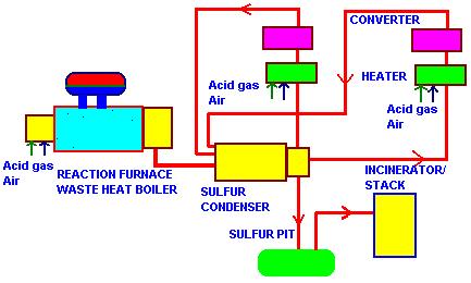
This is a simplified interpretation of the reactions taking place.The reaction is complicated by the existence of various species of gaseous sulfur. Fig below shows the scheme from heat recovery viewpoint.

There are basically 2 heat recovery systems.The reaction waste heat boiler recovers energy from the gas stream behind the sulfur burner ;the gas contains SO2,H2S,Sx,CO,CO2,H2,CH4,N2, and is cooled from about 2200-2400 F to about 600 F,generating 500-600 psig saturated steam. An elevated drum fire tube boiler is typically the design used ; this design helps protect the tube sheet and tubes through proper circulation.Ferrules are used at the inlet tube sheet to transfer heat flux away from the tube sheet into the region where boiling occurs,thus keeping the tube inlet and tube sheet region cool.A two-gas pass boiler may be used,though single pass designs are also available.Provision for sulfur recovery is made at the gas exit zone by using sulfur drains,which are kept warm by circulating steam. Since the gas pressure is atmospheric,casing designs are not special as in reformed gas boiler in hydrogen plants.Adequete refractory is used ensuring the casing is hot and is near or above the sulfur dew point of 350-370 F.Gas bypass systems are not generally used.Carbon steel tubes are adequete.Economizers are not recommended due to low temperature corrosion concerns.
The second stage of heat recovery takes the form of sulfur condenser; it is a low pressure steam generating section,where multiple low temperature gas streams leaving the various stages of catalytic conversion ranging from 350-500 F are cooled in the boiler generating 20-50 psig saturated steam.Here too the drains have to be kept warm to prevent solidification of sulfur.Carbon steel tubes are adequete. Single shell fire tube boilers are widely used for this application if the gas flow is small,as they are less expensive than elevated rum designs.Separate exchangers may be used for each stage of conversion if the gas flow is large.
SULFURIC ACID PLANTS
In the manufacture of sulfuric acid by the contact process,raw sulfur is burned in a combustor with air. The resulting gases containing SO2,N2,O2 at about 1800-1900 F and at a pressure of about 2 psig enter a waste heat boiler and the gas is cooled to about 750-800 F.The boiler could be of fire tube or water tube design,depending on the gas flow and economics.High pressure saturated or superheated steam is generated.The exit gas temperature is controlled as this is the optimum temperature for conversion of SO2 to SO3 in the converter,which follows the boiler.In the converter,catalysts convert most of the SO2 to SO3.Exothermic reactions occur and the gas stream is again cooled using superheaters or air heaters.After each stage of cooling,the gas stream enters the reactor for converting more of the sulfur dioxide to trioxide.In the final stage, an economizer is used.Finally the gas is absorbed in dilute sulfuric acid acid to form concentrated acid.A simple scheme for this process is shown below.
Though the gas stream behind sulfur combustor contains little water vapor,acid formation is likely if the air is moist and startups,shutdowns are frequent.Hence the casing has to be preferably a hot casing. A membrane wall design for water tube boilers is suggested as the tube walls can be kept above the acid dew point. The feed water temperature entering the economizer has to be above 280 F to minimize low temperature corrosion concerns.The casing design has to handle the high gas pressure. Soot blowers are not used as it affects the gas composition,which is critical to the process. Tube wastage due to potential corrosion is sometimes handled in Europe,Asia by using cast iron gilled tubes for economizers,though in the US,carbon steel finned tube economizers are widely used.Internal as well external gas bypass systems are used for the sulfur combustor waste heat boiler.Fire tube boilers if used are of elevated drum design with tube sheet/tube inlet region protected by refractory and ferrules.For more information on these designs,see my Waste Heat Boiler Deskbook.